First, let us understand the difference between grounding and earthing.
Whenever the DCS or PLC systems are grounded, they still not connected to the earth. The system has a ground bus bar inside located at an appropriate place to which all internal grounding connection is returned. Once the final ground bus bar is connected to an actual-earth pit or earth grid that the system finally earthed.
Improper earthing or grounding of Distributed Control System (DCS) or Programmable Logic Controller (PLC) may result in either mal-operation of the control system or a controller or failure of electronic cards or sometimes even embedded software gets erased.
In the case of DCS or PLC each cubicle is having a ground bus bar to which the controller chassis, shields can be connected. These bus bars are then returned to a final ground bus bar from where the connection is then taken to earth pit or earth grid.
The earth pit must have a small earth resistance ( much less than 1 ohm). usually, the earth resistance can be measured by a three probe method.
Grounding or Earthing Scheme

Types
There are four layers required for the correct and effective grounding and earthing.
- Isolated local Ground (G1)
- Isolated Common Ground Reference (G2)
- Control System Ground (G3)
- Dedicated plant earth Grid (G4)
Isolated local Ground (G1)
Isolated local Ground (G1) is where power supplies, internal power component enclosures, etc., are grounded on a bus bar. This refers typically to one control system.
Isolated Common Ground Reference (G2)
Isolated local Ground (G1) connection from each of the control systems, there within the realm is terminated along with the frame or cabinet or overall enclosures are individually terminated for grounding to create an Isolated Common Ground Reference(G2).
It should be noted that the enclosure earthing minimized the results of Electromagnetic interference.
Control System Ground (G3)
It is where the incoming power supply isolation transformer secondary is grounded along with ground connection obtained from Isolation common ground reference(G2). This control system ground is considered as the final earth pit for that location. It can be terminated on the dedicated plant earth Grid (G4).
The control system ground (G3) or the final earth pit connected to the local control systems should be separate earth pit. Which then can be connected to a dedicated plant earth system. This control system G3 should not be shared with other plant systems.
Dedicated Plant Earth Ground (G4)
The Dedicated plant earth ground (G4) may or may not exist. If exists it is supposed to have the lowest impedance. It consists of many earth pits in a grid fashion.
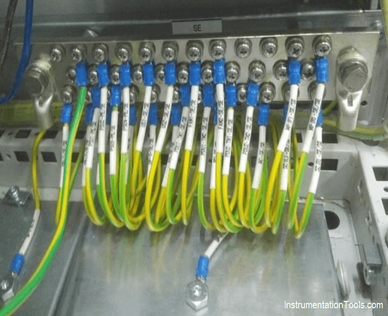
The cable used for grounding should be in green with yellow marks.
The ground bus bars to be used should be copper bus bars with approximately 10 mm as the thickness and 50 mm in width.
Selection of Components Used In Electrical Earthing or Grounding
The overall effectiveness of any grounding system will be determined by the individual components that are used to construct the system and the manner in which the components are connected. The purpose of this article will be to review the selection of these components and the methods by which they should be interconnected.
Great care must be exercised in selecting all of the following grounding components:
- The Grounding Conductors
- The Grounding Electrodes
- The Connectors
Grounding Components

The Grounding Conductors
The NEC contains requirements for both the equipment grounding conductors (EGC) and the grounding electrode conductor (GEC).
Recall that the EGC is used to connect the noncurrent-carrying metal parts of equipment, enclosures, raceways, etc., to the system grounded conductor and/or the grounding electrode conductor at the service or source of a separately derived system. The GEC, on the other hand, is used to connect the grounding electrode to the EGC and/or grounded conductor at the service or source of a separately derived system.
Equipment Grounding Conductors
Materials:
Section 250-91 (b) lists 11 components which are permitted to serve as the equipment grounding conductor for both branch-circuits and feeders. The permissible items are a copper or other corrosion-resistant conductor.
EGC’s are permitted to be either solid or stranded; insulated, covered, or bare; and in the form of a wire or a busbar of any shape, rigid metal conduit, intermediate metal conduit, electrical metallic tubing, flexible metal conduit where both the conduit and fittings are listed for grounding, armor of Type AC cable, the copper sheath of mineral-insulated, metal-sheathed cable, the metallic sheath or the combined metallic sheath and grounding conductors of Type MC cable, cable trays as permitted in Sections 318-3(c) and 318-7 of the NEC, cablebus framework as permitted in Section 365-2(a) of the NEC, other electrically continuous metal raceways listed for grounding.
Installation:
No matter what type of EGC is selected, the NEC requires in Section 300-3 (b) that in general, all conductors of the circuit, including the EGC must be contained within the same raceway, cable tray, trench, cable or cord.
The purpose of this requirement is to ensure the impedance of the EGC remains at the lowest possible value. When the circuit conductors are run in parallel, as permitted by Section 310- 4 of the NEC, the equipment grounding conductors are also required to be run in parallel. In these parallel installations the EGC must be a full sized conductor based on the ampere rating of the overcurrent protective device protecting the circuit conductors.
The NEC further requires in Section 250-92 (c) that the EGC shall be installed with all of the applicable provisions in the Code for the type of EGC which is selected. In other words, if rigid metal conduit (RMC) is used as the EGC, as permitted in Section 250-91 (b) (2), the RMC must be installed in a manner that meets all of the requirements for RMC contained in Article 346 of the NEC.
Installers of electrical systems should understand that when they install a raceway system, such as RMC, and it is used as an EGC, each length of conduit is part of the overall equipment grounding system. For this reason, any terminations at boxes or couplings must be made up wrenchtight to ensure a low impedance ground path.
Size:
When the equipment grounding conductor is a separate conductor, as permitted by 250-91 (b) (1), the size of the EGC is determined by the rating or the setting of the overcurrent protective device (fuse or circuit breaker) which is ahead of the equipment, conduit, etc.
Table 250-95 of the NEC contains the minimum size for aluminum, copper-clad aluminum and copper equipment grounding conductors. The table includes sizes for circuits from 15- amperes up to 6000-amperes. The values listed in the table are based on a maximum circuit conductor length of 100 feet.
For conductor lengths longer than 100 ft, an adjustment in the EGC size may be necessary. Section 250- 95 requires that where the circuit ungrounded conductors are increased in size to allow for voltage drop, the circuit equipment grounding conductors must be adjusted proportionately as well.
Grounding Electrode Conductors
Materials:
The grounding electrode conductor is permitted to be constructed of copper, aluminum, or copper-clad aluminum. Copper-clad aluminum is constructed of a minimum of 10% copper which is metallurgically bonded to the aluminum core.
The GEC is permitted to be a solid or stranded conductor and it can be an insulated, covered or bare conductor. Solid conductors provide less surface area to corrode and subsequently are used when installed in corrosive locations. However, stranded conductors in general are easier to work with so they are used more frequently.
With stranded conductors of a given size, the greater the number of strands, the smaller each strand is and the conductor is more flexible. Copper is by far the most common choice for grounding electrode conductors but copper-clad aluminum may be used to reduce the likelihood of repeated theft of the copper GEC.
The major disadvantage to using aluminum is the installation restriction in damp or wet locations. See installation provisions below.
Installation:
In general, grounding electrode conductors are required to be installed in one continuous length, without splices or joints. As noted above however, the GEC can be spliced by means of irreversible compression-type connectors listed for the use or by means of the exothermic welding process (CADWELD).
Also as noted above, the GEC can be installed directly on a building structure, if a No. 6 AWG or larger, and not subject to physical damage. If the GEC is going to be subject to physical damage it should be installed in a raceway or cable armor for protection.
Section 250-92 (a) prohibits the use of aluminum or copper-clad aluminum grounding electrode conductors when they are installed in direct contact with masonry, the earth, or where they are subject to corrosive conditions.
Another important restriction for aluminum or copper-clad aluminum GEC’s is the prohibition against their use outdoors within 18 inches of the earth. This requirement effectively precludes the use of aluminum or copper-clad aluminum for connection to “made” electrodes installed outdoors.
Size:
The size of the grounding electrode conductor is based on the size of the largest service-entrance conductor that supplies the building or structure. When the service conductors are installed in parallel, the size of the GEC is based on the size of the equivalent area of a single conductor.
For example, if a 3-phase, 4-wire service consists of two, 500 kcmil conductors per phase, in parallel, the size of the GEC would be based on the equivalent area of a single phase,1,000kcmil,( 500kcmil x 2 conductors). Table 250-94 of the NEC contains the minimum size for aluminum, copper-clad aluminum and copper grounding electrode conductors.
The table includes sizes for circuits from No. 2 AWG copper and No. 1/0 AWG aluminum up to 1100 kcmil copper and 1750 kcmil aluminum or copperclad aluminum. Designers and installers of electrical systems should note that no matter what the size of the service, the GEC is never required to be larger than a 3/0 AWG copper or a 250 kcmil aluminum or copper-clad aluminum conductor.
The reason for this limitation is that the grounding electrode is unable to dissipate any more current into the earth than can be carried by these conductors. So even if the conductor size were increased, the effectiveness of the grounding electrode system would not be improved.
There may be particular applications where design personnel oversize the grounding electrode conductor because of the size of the facility or the nature of the equipment which may be used in the facility. For large facilities where outdoor equipment and exposed conductors are used, available fault current and maximum clearing times must be considered. IEEE Std 80 gives guidance for choosing conductor size and material.
The Grounding Electrode
Many different types of grounding electrodes are available, some “natural” and some “made”. The natural types include metal underground water pipe, the metal frame of the building (if effectively grounded), copper wire or reinforcing bar in concrete foundations or underground structures.
“Made” electrodes are specifically installed to improve the system grounding or earthing. Made electrodes include rods or pipe driven into the earth, metallic plates buried in the earth or a copper wire ring encircling the structure. Note that underground gas piping is not permitted to be used as a grounding electrode. Likewise, aluminum electrodes are prohibited by the NEC.
Other rules for the above electrodes also may apply. Those in effect at the time of this writing include:
Rule #1
All water pipe electrodes must be in contact with the earth for at least 10 feet and must be supplemented by an additional electrode as listed above. (If the water pipe happens to be disconnected or if a section of plastic pipe is installed at a later date, the supplemental electrode would still be effective.)
Rule #2
The copper conductor in the concrete foundation or footer must be #4 AWG or larger and must be at least 20 feet if it is to be used as a grounding electrode. If rebars are used, they must be 1/2 inch (#4) or larger, bare or coated with an electrically conductive material and at least 20 feet long. The foundation must be in direct contact with the earth.

This type of electrode is commonly called a “Ufer Ground”. (A plastic sheet must not be used to separate the concrete from the earth.) Figure 1 shows a #4 AWG or larger copper wire imbedded in the concrete foundation. Figure 2 shows a #4 (1/2”) or larger rebar imbedded in the concrete foundation. CADWELD Connections are used to make permanent connections to either the copper wire or the rebar.
Rule #3
The copper wire ground ring encircling a building or structure must be #2 AWG or larger, at least 20 feet (6 m) long and buried at least 2 1/2 feet (.76m) in the earth.
Rule #4
Rod or pipe electrodes shall be at least 8 ft long with a minimum of 8 feet in contact with the earth, installed vertically except where rock is encountered, in which case they may be driven at a 45o angle or buried in a trench 2 1/2 feet deep. The upper end of the rod or pipe must be flush or below grade unless the top end and the connector are protected from damage.
Pipe electrodes shall be 3/4 inch trade size or larger and shall have their outer surface galvanized or another metal coating for corrosion protection. Rod electrodes shall be 5/8 inch diameter if of iron or steel. Stainless steel rods less than 5/8 inch and nonferrous rods, including copper clad steel rods, shall be listed and not less than 1/2 inch diameter.
Rule #5
Plate electrodes must be at least 1 square foot (0.093 square meter) and 1/4 inch (6.3 mm) thick if steel or 0.06 inch (1.5 mm) thick if nonferrous. Note the plate thickness required by the NEC is different than that required for lightning protection. Burial depth is not specified by code. If used, we suggest that to get the best performance, it be installed on edge and with the top at least 18 inch (460 mm) below grade. Plate electrodes, however, are not as efficient as most other types of electrodes and are usually used only in special conditions where other types of electrodes cannot be used.
Instrumentation Earthing
Transfer of the immediate discharge of the electrical energy directly to the earth by means of the low resistance path is known as the earthing.

Main objective of the earthing system in plant is described as below:
- It provides low impedance path to ensure the proper function of system under fault condition
- It ensures that personnel are not exposed to unsafe potential due to uncleared fault
- It ensures compliance to EMC requirements
- IS earth avoids ignition sources in Hazardous Area.
Items or equipment which require earthing, are but not limited to below,
- field instruments,
- control system cabinets,
- analyzer shelters,
- junction boxes,
- enclosures,
- ducts,
- cable trays,
- stanchions,
- field local panels,
- Consoles,
- Motors,
- Tanks,
- vessels,
- pipes,
- steel structure, etc.
This article mainly focuses on earthing requirements for instrumentation items of any industrial plant.
Types
There are mainly 3 types of earthing systems provided for instrumentation.
- Safety Earth (SE) / Dirty Earth / Protective Earth / Electrical Earth / Power Earth
- Instrument Earth (IE) / Electronic Earth / Reference Earth / Clean Earth / Signal Earth
- Intrinsic Safety (IS) Earth for IS circuit. This is only required when you have IS instruments.
Instrument Earth
The primary aim of the instrument earth/signal earth is to provide a low impedance path to the noise currents induced by RFI/EMI, which may result in the induction of faulty unwanted noise signals into the analog signals.
Shields of Single pair /Multi pair analog instrument signal cables are connected to this earth (IE).
Safety Earth
Undetected earth faults pose safety risks to personnel also may lead to safety hazards such as equipment malfunctions, fire, and electric shock. That is why we need electrical earth / Safety earth.
Earth Resistance
Allowable earth resistance as per codes or control system vendor recommendation should be considered for Instrument Earthing system design.
Below is a reference table that can be updated based on the project-specific requirement.

There should be isolation between each type of earthing mentioned above. If there is no isolation which means that the purpose of the above earthing requirement will not be fulfilled.
There are mainly two areas in which earthing system is envisaged.
- Indoor (Building like control room, Switch-gear rooms etc where cabinets/panels/consoles etc are installed)
- Outdoor (Process area where instruments and related installation items are installed)
Control panels inside the control room fall under the Indoor type. Depending upon the cabinet’s functions each type of earthing bars are provided.
Control room equipment including system cabinet & marshaling cabinets, power distribution panels, Packaged control system cabinets, Workstations, Auxiliary consoles, printers, etc. should be considered for earthing requirement.
e.g. System and marshaling cabinets should have – SE, IE and IS Earth bars.
Network cabinets / server cabinets / Power distribution panel should have – SE only.
Within the Cabinet, the Instrument Earth bar shall be isolated from the Safety Earth bar by mounting the Instrument Earth bar on insulating buses.
All the instrument earth bars in the cabinets should be connected to a common instrument earth bar provided in the false floor / Cable cellar using an insulated redundant copper conductor cables.
This common Instrument Earth bar shall be further connected to the nearest Instrument earth grid using copper cables.
It should be agreed with the Control system supplier for earthing philosophy of Cabinet’s earth bar connection with the building earth bar network. E.g. Star connection or series connection.
Earthing philosophy should cover Scope of supply, grounding wire/strip sizes, earth stud size, wire color as a minimum.
Series Earth Connectivity

Start / point to point Earth connectivity
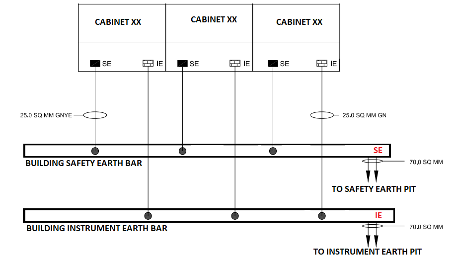
All the safety earth bars in the cabinets should be connected to a common safety earth bar provided in the false floor / Cable cellar using insulated redundant copper conductor cables.
This common Safety Earth bar shall be further connected to the nearest safety earth grid using copper cables. The Main Earth grid conductor size can be calculated based on the desired fault current within the required time to be earthed.
Ultimately, this network/grid is connected to earth pits. The surrounding soil of the earth pit must be kept moist. The effect of the soil temperature on soil resistivity is more influencing near and below the freezing point, which will result in the installation of the earth electrode at the depth to which frost will not penetrate.
Good Practices
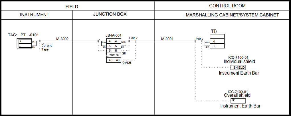
- Cable shield shall be insulated and floated at the field instrument side (Cut and Tape). Cable Shield is the drain wire attached with Aluminum Mylar or metal braid cover on the instrument signal cables i.e. 4-20mA analog signal, low voltage digital signals, etc
- Main cable (i.e. from Junction box and control room) shields shall be grounded at one place i.e. control system end Instrument earth bar Isolated type. All the connections to the Instrument Earth bar within the cabinet shall be of screw type of non-corrosive metal.
Similarly, for IS cable, individual and overall shield shall be connected to the IS earth bar inside the cabinet.
Ensure continuity of all earth cables up to earth bar & up to earth pits.
- Cable armors shall be earthed at both ends for lightning protection i.e. at the junction box and at the control system end. Since the Junction box body and Control system cabinet body is connected to the Safety earth bar, cable armors are ultimately connected to the safety earth.
- All instruments (24V DC or 110 V /220V AC operated) body should be earthed to the nearest field safety earth bar located on the Steel structure.
- Earth continuity should be ensured between tray, tray fittings, and tray sections. This will be ensured by Earth cable/strips at every 25 meters of tray length.
- Earth bar connection should be such that painting should not act as bad contact between earth bar and Structure. Continuity shall be ensured.
Junction Box Earthing (Safety Earth)

Transmitter Earthing (Safety Earth)

Junction Box shield Termination on Isolated Instrument Earth terminals

Instrument Cable Tray Earthing (Safety Earth)

Instrument Earth inside the Control System cabinet (Isolated from Safety Earth)

Safety Earth inside the Control system cabinet (Non Isolated)
Importance of Grounding Electronic Equipment
Grounding electronic equipment for personal safety and clearing of faults is no different than that of any other equipment. Safe grounding requires fast opening of circuit breakers or fuses and minimization of voltage differences between exposed metal surfaces on all of the involved electrical system and equipment, to levels that are safe for people.
What makes electronic systems different is the sensitivity of their circuit components to relatively small transient currents and voltages. It is also inherent in the nature of solid state devices to be very fast, so they are affected by equally “fast” electrical disturbances. Even lightning is a slow transient compared to the response of almost any electronic device.
Typical threats to proper operation of electronic devices and systems include:
1. Lightning
Direct strikes, but the effects also include overhead cloud-to-cloud, and nearby strikes causing induced voltages
2. Switching Transients
Switching transients from power network operations and power factor capacitor switching, lightning arrestor operation, and fault clearing activities- especially on nearby power circuits.
3. Static electricity
Directly applied arcs to the equipment, but sometimes arcs near the equipment will also affect the equipment.
4. Electrical fast transients
Typically as caused by arcing contacts or collapsing magnetic fields in the coils of contactors in equipment, usually very near the affected equipment
Basics of Transient Problem Solving
Solving transient problems is never easy. They may be random or repetitive. In general, they have waveshapes which are not easily analyzed. Transients though are capable of being tamed by:
- Limiting overvoltages (surge voltages) on the ac power conductors with surge protective devices (SPDs)
- Reducing the chances of electrical noise getting on power circuits connected to electronic equipment and the data signal circuit cables that interconnect the units of equipment. This can often be accomplished by observing the requirements for proper routing and grounding of branch circuits including their conduits, and ensuring adequate separation of power and data signal wiring.
- Proper grounding involving the correct installation of equipment grounding conductors of all types, and neutral terminal grounding and bonding at the service entrance and for separately derived ac systems.
While the above are all within the scope of the contractors’ job, we want to emphasize that the equipment supplier can and must provide equipment that can “live within” practical levels of transients as are known to exist on the typical commercial and industrial site. Otherwise, extensive effort and great expenditures may be needed in order to get this kind of too-sensitive equipment to work in an acceptable way.

Interconnected Electronic Equipment Systems
This section deals with grounding of electronic systems that are interconnected by signal, data, or telecommunications cables. It is helpful to think in terms of two kinds of grounding with this kind of equipment:
- Safety grounding for fire and personnel protection. This kind of grounding also helps to provide for the protection of equipment to minimize damage from electrical system faults and transients such as lightning.
- Performance grounding for the protection of data circuits and solid-state components within various items of interconnected equipment making up an electronic system. Sometimes this is called “computer” or “electronic” grounding but these are not very accurate terms. Note that the protection of data circuits does not have to involve earth grounding electrode connections, although good grounding to the building service equipment’s grounding electrode system makes this protection a lot easier.
For example and as mentioned above, airplanes flying through lightning storms have no earth grounds connected to them but, while experiencing lightning hits, are probably safer than many land-based systems. And after a lightning strike all of the electronic equipment within the aircraft is expected to continue to work in flawless fashion.
Some Important Points About Grounding
Point #1
Typically the safety grounding of equipment is exactly the same for electronic equipment as it is for any other kind of apparatus, whether it is a refrigerator or a printing press. The “green wire” and conduit/raceway system’s grounding which is well documented in the NEC and other codes, defines these requirements completely.
Safe equipment grounding requires fast clearing of circuit breakers or fuses and minimization of voltage differences on exposed metal surfaces of equipment to levels that are safe for people. This is called the control of “touch potential.” There is absolutely no conflict between NEC defined grounding and the more specialized grounding and bonding practices described in (2) below.
An unnecessary conflict can be created however, such as when someone attempts to create a “separate”, “dedicated” or “clean” grounding connection that is not permitted by the NEC!
Point #2
Protection of data circuits generally requires additional considerations beyond the intent of the NEC, but not in violation of it. Protection of data circuits from disruption or even damage does not always involve grounding, although good grounding makes this protection a lot easier.
Aircraft have no earth grounds while they are flying. The airplane carries its own “grounding” system for its ac and dc systems, and signal grounding purposes. This grounding system is entirely metallic in nature and it is often called a self contained power and signal reference system, which is a more accurate description. Even direct lightning “hits” are not likely to cause equipment damage or even disruption to signals.
Point #3
The circuits of most electronic systems are almost always sensitive to voltages of a few tens of volts or even to as little as one or two volts. As a result, these systems are designed with great care to keep transients out of the actual circuitry and off of the signal paths between interconnected units of a system.
To accomplish this, some equipment uses electrostatically shielded isolation transformer techniques and ac-dc power supplies designed to reject transients. However, for these techniques to be fully effective, good grounding and bonding practices exceeding those required in the NEC, must often be employed.
Point #4
Data signals inside most electronic systems consists of bits of information processed as square waves or impulses at about 5 volts in amplitude and clock speeds which can exceed 200 MHz. Data transferred between equipment often has a magnitude of 12-18 volts, and the speed of transfer is lower than that of the signal processing speed available inside of the equipment.
In any case, the signal rise-times of the clock and most other signal pulses such as those used to transfer bits, are far faster than the typical lightning strike. Yet, even at these speeds the systems can be made to have high reliability and to be relatively immune to interference if good grounding and bonding practices are followed.
Point #5
Lightning related waveforms are usually the “worst case” situation for transients on most ac power system wiring and related grounding systems.
This makes lightning the principal threat. More information about lightning and its typical waveforms may be obtained by consulting ANSI/IEEE Std C62.41-1992
Point #6
Fast electrical transients are created in some equipment with electromechanical contactors. The interference problem from these items could be serious, but it is easy to solve by installing RC snubbers (consisting of resistors and capacitors) across the contacts, coils, or both items of the offending device. This kind of interference with electronic circuits can sometimes be controlled by more stringent shielding, or grounding and bonding practices.
However, the root cause of this kind of problem is really not a shielding, or grounding and bonding related problem. Instead it is an equipment circuit modification problem and this is the kind of thing which typical electrical contractors should normally not be expected to identify or to solve.
Harmonics
Note that by itself, harmonic current and voltage generation is not a grounding problem unless due to a miswired circuit or a component’s failure in which some of the harmonic current gets impressed onto the equipment grounding system. In this case, the effort is not to stamp-out the harmonics, but to find the miswire or failed component and to effect the repair.
Harmonics are often an important safety concern on the neutral conductor of a three-phase, wye-connected ac system where it is supporting line-to-neutral connected nonlinear loads- such as computers, etc. In this case the entire neutral path must be increased in ampacity to as much as 200% of the ampacity used for the related line conductors. This is regularly done in order that a fire be avoided due to current overload from third harmonic and other odd multiple harmonics called “triplens”.
Other steps may be required to prevent harmonics from interfering with proper system operation. However, the exact method and point chosen for grounding of the neutral conductor at the ac supply source, will not improve any problems associated with harmonics. Ungrounding of the neutral is likely to be an NEC violation in almost all designs, and would decrease personnel safety.
Harmonic Current Filters (Traps)
Harmonic filters commonly called “traps” are not grounding problems unless they are miswired to direct the current through them into the equipment grounding system. This is an unusual situation and involves an NEC violation which would need correction. Typically, the trap is connected line-to-line, line-to-neutral, or both, but never to equipment or any other ground.
Surge Protective Devices (SPD) And Grounding Connections
In addition to line-to-line and line-to-neutral connections, surge protective devices (SPDs) are also connected to the circuit’s equipment grounding conductor.
Any transient voltage which then operates the SPD and causes current flow through it and to the equipment grounding conductor, raises the ground potential as measured at the installation point of the SPD and to the remote “ground” used as a zero voltage reference. Because SPDs may be subject to very high voltages with steep (e.g., fast rise time) wavefronts, the concurrent effects on the grounding system may be very severe.
Some Practical Recommendations
These are some of the practical electrical installation considerations we recommend:
Recommendation #1
Field installed electrical grounding/bonding conductors routed between the metal frame or enclosures of separate units of electronic equipment should be connected to the NEC “green wire” grounding system at both ends, not isolated or insulated from it.
Recommendation #2
Isolation transformers with electrostatic shielding between the windings are readily available and should be employed to interface the electrical system to the panelboard used to supply branch circuit power to the electronic equipment. The installation of both the transformer and panelboard(s) should occur as physically close to the served electronic equipment as is possible.
Note that the electrostatic shielding can provide useful attenuation of most types of common mode transients up to about 1000:1 (e.g., -60 dB). Attenuation figures above this value are generally unrealistic and are not likely to be provided by a transformer that is installed into a real-world installation and in conformance with the NEC. In any case, follow the transformer manufacturer’s recommendations closely to achieve the maximum benefit, but only if the instructions conform to the NEC.
Recommendation #3
Interconnecting cables between electronic system enclosures in equipment rooms should be routed in close proximity to the structural subfloor. This is especially the case if it contains substantial metal structures that are well grounded such as steel decking, etc.
The best results however, are obtained when these cables are laid in close proximity to a specially installed signal reference grid, such as is recommended to be installed under a raised floor normally used in a computer room. If interconnecting cables are routed between locations in a cable tray or wireway, then the use of random lay is preferred rather than “neat” bundling in these forms of raceway.
(This is recommended as random lay decreases the coupling of noise from one adjacent conductor into the other when they are laid parallel to one another for any significant length.)
Recommendation #4
If wireways are used to route cables, they should be made from metal, be well and continuously grounded and bonded, and be equipped with a tight cover such as one fastened by screws. Ladder tray is less desirable than solid-bottom tray.
Recommendation #5
Field installed data cables should normally be separated from power cables and conduits to the greatest practical distance. This reduces unwanted coupling between the two circuits. To avoid noise coupling problems where one circuit crosses over or under the other, try to make the crossover at rightangles.
Recommendation #6
Where metal raceways or conduits are used to contain interconnecting data cables, it is recommended that additional bonding connections be made at several points along their entire length (Black plate) to ensure good longitudinal coupling.
In addition to being well grounded/bonded to the equipment at the ends of the run, the conduit or raceway should also be bonded to any nearby structural steel along the run.
Recommendation #7
All metallic piping, ducting, conduit/raceway, wireway and cable tray located within 6 feet (horizontal or vertical) of any installed Signal Reference Grid (SRG) must be bonded to the SRG. This is especially important where these conductors enter or leave the area defined by the SRG. If this is not done, then lightning side flash may occur from the above or any nearby grounded metal items to the SRG.
A side flash can cause a fire, electronic circuit damage, or both. More about the subject of side flash may be obtained by reference to ANSI/NFPA780-1995, the National Lightning Protection Code.
Recommendation #8
In addition to any NEC requirements, the neutral terminal, such as the Xo terminal on a wyesecondary connected transformer of a separately derived system, should be connected to the SRG and if available, also to the closest building steel.
Recommendation #9
Be sure to bond the SRG to any nearby accessible building steel so as to create many points of grounding/bonding. This is important to do along the SRG’s perimeter and for any steel that penetrates the SRG’s surface.
Recommendation #10
Grounding for ac systems and equipment must conform completely to NEC requirements. Also, if the electrical or electronic equipment has been tested and listed by an NRTL (Nationally Recognized Testing Laboratory, such as UL), then there may be additional or special grounding/bonding requirements which must also be met if proper operation is to be obtained.
Again, any use of a “dedicated”, “clean” or other non-NEC allowed connection, such as one which is separated from the building’s service grounding electrode and the associated equipment grounding conductor system, is totally against the intent of this article. Only grounding systems and connections which meet National Electrical Code requirements are suitable.
Recommendation #11
Special care must be used to assure proper grounding if NEC permitted isolated grounding is specified. “Isolated/Insulated grounding” (IG) must be per NEC Section 250-74; Connecting Receptacle Terminal to Box; exception No. 4; and Section 250- 75, Bonding Other Enclosures for field wired (e.g., direct) branch circuit connections to electronic equipment.
Recommendation #12
In particular, no attempt must be made during or after installation to separate the electronic system’s equipment grounding conductors from the ac power system’s equipment grounding conductors and its associated earth electrode grounding connections.
Such separations would violate the NEC and produce potential electrical fire and shock hazards. They would also be likely to damage circuits inside the related electronic equipment, or to at least degrade the operation of it.
Recommendation #13
Note that the use of the IG method even if it follows NEC requirements, does not always improve the performance of equipment. In fact, the use of the IG wiring method is just as likely to make things worse or to result in no observable change to the operation of the equipment.
There is usually no way to predict the benefits if any, of isolated ground circuits except by direct observation and comparison between solid grounding (SG) and IG methods in each case.
Recommendation #14
It is relatively easy to convert existing IG circuits to SG circuits on an as-needed basis. On the other hand, it is generally both impractical and not cost effective to convert an existing SG circuit to an IG style that conforms to NEC requirements.
Accordingly, circuits used to supply power to electronic equipment can be designed and first installed as IG types, so that they may later be converted back and forth between IG and SG as needed.
Recommendation #15
The equipment grounding conductors in a feeder or branch circuit must always be routed within the same conduit or raceway containing that circuit’s associated power circuit conductors. This also applies to flexible cord and cable assemblies.
Recommendation #16
Where transfer switches (including those found in UPS systems) are used, the possibility of common mode noise is not removed. Proper grounding between alternate sources of power is required, usually by solid interconnection of the two system’s neutrals, but with only one of the two ac systems being the one with the neutral grounded.
Unless the two involved ac systems are installed physically adjacent to one another, a ground potential shift disturbance may occur during transfer operations on the switch. This shift in ground potential can then unwantedly introduce common-mode noise into the load being served by the switch.
Recommendation #17
Ground potential-shift problems and common-mode noise problems in general are avoidedan isolation transformer is installed adjacent to the served loads and is positioned between the output of a transfer switch and the input of the served electronic loads.
In these cases the neutral terminal on the secondary of the isolation transformer is solidly grounded and both the transformer and electronic load equipment are made common to one another for broadband grounding purposes, if they are also connected to an SRG that has been installed in the equipment room and just beneath the equipment
Recommendation #18
More than one isolation transformer may be used in the above manner if the site is large. For example, multiple isolation transformers installed and grounded to an SRG in an equipment room are a recommended practice for larger sites.
Also, multiple, separated, but SRG equipped rooms may each be provided with its own isolation transformer and grounded as above.
Recommendation #19
Specially designed, “original” forms of grounding which are not in literal compliance with NEC requirements are not recommended. This includes approaches to grounding called “clean”, “dedicated”, “single point” and other forms of “isolated” grounding not permitted by the NEC.
The authors are aware of instances where all grounds are initially properly connected together with a jumper which the owner or operator can later remove at his discretion. Since removal of this connection creates both an NEC violation and fire/shock safety hazard, the authors do not recommend this approach!
Recommendation #20
Surge Protective Devices (SPD) provide overvoltage protection at various points for power and data circuits wherever they are properly applied. Proper use of SPDs is highly recommended.
Recommendation #21
After the electrical installation is complete, a careful inspection of the wiring is needed to ensure safety and performance criteria have all been met.
Regarding grounding, the following should be part of the inspection process:
Rule 1
Misidentification of conductors such as the neutral and “green wire” safety grounding conductors, often occurs. The problem shows up at the point where they terminate. A mistake of this kind is a serious violation of NEC Section 250-21, and others.
Cross-connection between neutral and ground conductors results in unwanted current flow in the equipment grounding system, but will normally not cause an overcurrent protection device to operate. Hence, there is often no immediate indication of a problem such as when the power is first applied. Therefore, these conductors and connections need to be verified before power is applied.
Rule 2
All metallic conduit, wireway, raceway and other metallic enclosures, must be wellbonded along their length to ensure end to end continuity.
They should also be well grounded at multiple points along their length to building steel and SRGs within 6 feet to provide effective high frequency grounding. Effectively grounded, end terminations to and from served equipment are most important.
Rule 3
Ensure that the shortest possible lead length has been used to connect SPDs to the conductors they are protecting. Ideally, the SPD would be mounted directly on or inside the equipment it protects.
External mounting in a separate enclosure and a conduit connection to the protected equipment creates longer distances between the SPD and the load it protects. This decreases the effectiveness of the protection.
Rule 4
Any connection that is not a good electrical connection over the life of the installation is potential trouble. Such a poor connection can be a cause of noise or of a total interruption of the signal process or power continuity. Either a connection is made properly, or it must be reworked to bring it within specifications.
Ground Current Interference With Cathode Ray Tube (CRT) Based Equipment
Low frequency magnetic fields such as those associated with the power system’s fundamental of 60 Hz and harmonics from it, will sometimes be seen to interfere with the normal deflection of the electron beam being used to paint the image on the CRT’s screen. This magnetic field interference is seen by the equipment’s operator as a wavy or rippling display that is often very disconcerting to the operator. (See Fig. 1)

One way magnetic fields of the type involved in this kind of interference are created in grounding conductors is by any continuous or nearly so, flow of current in externally attached supplementary equipment grounding conductors, grounding electrode conductors, structural steel members, piping, ducting, cable trays, wireways, etc. Stray ground currents in any of these items can produce the same effects on the CRT’s screen.
Fortunately, the effects of these interfering magnetic fields falls off exponentially with distance between the source of the field and the equipment that is being affected. Also, the orientation of the CRT to the lines of force of the magnetic field affects the severity of the problem. Therefore, increased spacing and reorientation of equipment is often the first and a successful step, in the resolution of the problem.
Another practical approach to reducing the effects of magnetic fields on a CRT is to increase the number and location of any grounding/bonding connections between grounded items, including the one involved in the interference. For instance, more bonding between cold water piping, building steel, and grounding electrode conductors often solves the problem. (See Fig. 2)

The foregoing procedure generally works since it breaks up the currents from one conductor into several smaller ones. In example, since the magnetic field surrounding a conductor is proportional to the current’s amplitude, the process of providing multiple paths for a current reduces the current in any one conductor and therefore the stray magnetic field being emitted from it.
The best approach of all however, is to find out how the unwanted current is getting into the conductor and to fix the problem in accordance with NEC requirements such as per Section 250-21, Objectionable Current On Grounding Conductors.
How to Avoid Bad Grounds ?
Earthing of electrical systems is required for a number of reasons, principally to ensure the safety of people near the system and to prevent damage to the system itself in the event of a fault.
The function of the protective conductor, or earth, is to provide a low resistance path for fault current so that the circuit protective devices operate rapidly to disconnect the supply.
The NEC, National Electrical Code defines a ground as: “a conducting connection, whether intentional or accidental between an electrical circuit or equipment and the earth, or to some conducting body that serves in place of the earth.”
When talking about grounding it is actually two different subjects, earth grounding and equipment grounding.
Earth grounding is an intentional connection from a circuit conductor usually the neutral to a ground electrode placed in the earth.
Equipment grounding is to ensure that operating equipment within a structure is properly grounded.
These two grounding systems are required to be kept separate except for a connection between the two systems to prevent differences in potential from a possible flashover from a lightning strike.
The purpose of a ground besides the protection of people plants and equipment is to provide a safe path for the dissipation of Fault Currents, Lightning Strikes, Static Discharges, EMI and RFI signals and Interference.
Improper grounding can create a lethal hazard. Correct grounding is essential for correct operation and safety of electrical equipments.
Grounding can solve many problems, but it can also cause new ones. One of the most common problem is called “ground loop”.
Consideration of ground can be very complex and application specific. But in many of these applications, when we make wired connections to ground and to electrical equipment, there are a few rules of thumb that are helpful:
- For isolated power applications where a connection to earth ground is not apparent, ground should be chosen as the common return path from power supply (DC minus). It may be necessary to hard-wire earth ground to this point if an earth ground connection is not already made by the power supply.
- Do not ground a signal at more than one point. Typically a signal is grounded at its source (including its shield).
- In general, as stated above, we try to never ground a cable at both ends. But one possible exception to this rule is when we are grounding cable shields in small signal applications. For most applications where only small differences in potential exist between grounds at each end of the cable, our equipment will work better when its shield is grounded at each end of the cable (at a minimum, ground it at the end closest to the noise source). Another exception is where your equipment connects to power, as DC powered equipment will often connect earth ground at the power supply minus terminal, but you should additionally include a connection to ground local to the instrument. This is done not only to stabilize applied voltages, but also because internal suppression devices in the instrument need a local, low resistance, low inductance path to shunt potentially destructive energy.
- For EMC purposes, a wired signal between devices should have earth ground applied at the end of the cable nearest the noise source of the signal, or nearest the noisiest device. Failure to provide a path to ground at the “origin” of the noise may result in the cable and/or its shield becoming an antenna for this noise, increasing its power and spread into other areas of the circuit, as well as potentially increasing system emissions.
- Do not use the chassis of the device as the ground conductor (i.e. make only one ground connection to the chassis). Note that many devices are required by code to have a safety ground connection to their metallic chassis or enclosure, but the chassis should never be used as a return path for load current to the device (for “safety” ground, it is sometimes used only as a return path for fault current). Note that the chassis connection to earth ground is sometimes used as the center of a star grounding scheme for the enclosed circuit.
- Many instruments are housed in plastic enclosures and may not make a connection to earth ground via their chassis. These instruments usually rely on direct-wired connections to earth ground at their terminals, as directed in their connection diagrams. In general, signal connections to these devices should be earth grounded at the end of the I/O cable nearest the instrument. This is because the instrument needs a low-impedance/low-inductance path to earth ground locally, to allow its various filters, capacitors, and transient suppression devices to shunt potentially destructive energy to earth ground without being impeded by high levels of inductance and resistance in the path to earth.
- Do not bundle noisy or high-energy signals or power with low level signals. Route all AC power wires away from sensitive signals and signal paths.
- Do not duplicate ground connections to the main power line at different points—try to connect all AC powered devices to the same power outlet when possible and safe. Similarly, use a star-grounding concept when making ground connections to your circuit.
- Do not combine or bundle isolated signals in the same shield or conduit.
- Do not allow conductive material to float unattached to any ground (it should connect to ground at one point).
- Do not leave unused shielded conductors in a bundled cable disconnected from ground. Ground unused conductors of a bundle at the load. In general, ground the cable shield at the signal source (or at both ends).
- Minimize the length and loop area of the wires that break-out from a bundled or shielded cable, just before the wires make their connection to the equipment.
Earthing of electrical systems is required for a number of reasons, principally to ensure the safety of people near the system and to prevent damage to the system itself in the event of a fault.The function of the protective conductor, or earth, is to provide a low resistance path for fault current so that the circuit protective devices operate rapidly to disconnect the supply.
The NEC, National Electrical Code defines a ground as: “a conducting connection, whether intentional or accidental between an electrical circuit or equipment and the earth, or to some conducting body that serves in place of the earth.”
When talking about grounding it is actually two different subjects, earth grounding and equipment grounding.
Earth grounding is an intentional connection from a circuit conductor usually the neutral to a ground electrode placed in the earth.
Equipment grounding is to ensure that operating equipment within a structure is properly grounded.
These two grounding systems are required to be kept separate except for a connection between the two systems to prevent differences in potential from a possible flashover from a lightning strike.
The purpose of a ground besides the protection of people plants and equipment is to provide a safe path for the dissipation of Fault Currents, Lightning Strikes, Static Discharges, EMI and RFI signals and Interference.
Improper grounding can create a lethal hazard. Correct grounding is essential for correct operation and safety of electrical equipments.
Grounding can solve many problems, but it can also cause new ones. One of the most common problem is called “ground loop”.
Consideration of ground can be very complex and application specific. But in many of these applications, when we make wired connections to ground and to electrical equipment, there are a few rules of thumb that are helpful:
- For isolated power applications where a connection to earth ground is not apparent, ground should be chosen as the common return path from power supply (DC minus). It may be necessary to hard-wire earth ground to this point if an earth ground connection is not already made by the power supply.
- Do not ground a signal at more than one point. Typically a signal is grounded at its source (including its shield).
- In general, as stated above, we try to never ground a cable at both ends. But one possible exception to this rule is when we are grounding cable shields in small signal applications. For most applications where only small differences in potential exist between grounds at each end of the cable, our equipment will work better when its shield is grounded at each end of the cable (at a minimum, ground it at the end closest to the noise source). Another exception is where your equipment connects to power, as DC powered equipment will often connect earth ground at the power supply minus terminal, but you should additionally include a connection to ground local to the instrument. This is done not only to stabilize applied voltages, but also because internal suppression devices in the instrument need a local, low resistance, low inductance path to shunt potentially destructive energy.
- For EMC purposes, a wired signal between devices should have earth ground applied at the end of the cable nearest the noise source of the signal, or nearest the noisiest device. Failure to provide a path to ground at the “origin” of the noise may result in the cable and/or its shield becoming an antenna for this noise, increasing its power and spread into other areas of the circuit, as well as potentially increasing system emissions.
- Do not use the chassis of the device as the ground conductor (i.e. make only one ground connection to the chassis). Note that many devices are required by code to have a safety ground connection to their metallic chassis or enclosure, but the chassis should never be used as a return path for load current to the device (for “safety” ground, it is sometimes used only as a return path for fault current). Note that the chassis connection to earth ground is sometimes used as the center of a star grounding scheme for the enclosed circuit.
- Many instruments are housed in plastic enclosures and may not make a connection to earth ground via their chassis. These instruments usually rely on direct-wired connections to earth ground at their terminals, as directed in their connection diagrams. In general, signal connections to these devices should be earth grounded at the end of the I/O cable nearest the instrument. This is because the instrument needs a low-impedance/low-inductance path to earth ground locally, to allow its various filters, capacitors, and transient suppression devices to shunt potentially destructive energy to earth ground without being impeded by high levels of inductance and resistance in the path to earth.
- Do not bundle noisy or high-energy signals or power with low level signals. Route all AC power wires away from sensitive signals and signal paths.
- Do not duplicate ground connections to the main power line at different points—try to connect all AC powered devices to the same power outlet when possible and safe. Similarly, use a star-grounding concept when making ground connections to your circuit.
- Do not combine or bundle isolated signals in the same shield or conduit.
- Do not allow conductive material to float unattached to any ground (it should connect to ground at one point).
- Do not leave unused shielded conductors in a bundled cable disconnected from ground. Ground unused conductors of a bundle at the load. In general, ground the cable shield at the signal source (or at both ends).
- Minimize the length and loop area of the wires that break-out from a bundled or shielded cable, just before the wires make their connection to the equipment.
Where should we Terminate the Cable Shields ?
A shielded cable is an electrical cable of one or more insulated conductors enclosed by a common conductive layer. The shield may be composed of braided strands of copper (or other metal, such as aluminium), a non-braided spiral winding of copper tape, or a layer of conducting polymer. Usually this shield is covered with a jacket. The shield acts as a Faraday cage to reduce electrical noise from affecting the signals, and to reduce electromagnetic radiation that may interfere with other devices.
The effectiveness of a cable shield installation depends on the kind of EMI to be shielded and the type of termination at both ends. This paper depicts the different types of cable shielding. Moreover shielding effectiveness is analyzed.
Shielding reduces electrostatic or capacitive coupled electrical noise in signal cable or communications cable
Electrostatic or capacitive coupling is proportional to the capacitance between the noise source and the signal wires. The magnitude of the interference depends on the rate of change of the noise voltage and the capacitance between the noise circuit and the signal circuit.
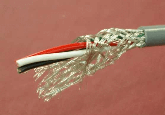
Electrostatic noise can be addressed by installing an electrostatic shield (also called a drain) around the signal wires. The currents generated by the noise voltages prefer to flow down the lower impedance path of the shield/drain rather than the signal wires.
The shield/drain must be of a low resistance material such as aluminum or copper. For a loosely braided copper shield (85% braid coverage), the screening factor is about 100 times or 20 dB. For a low resistance multi layered screen, this screening factor can be 35 dB or 3000 times.
The shield should be insulated to prevent inadvertent contact with multiple ground points, which could result in circulating currents.
The shield should never be left floating because that would tend to allow capacitive coupling, rendering the shield useless.
A single point connection to ground attempts to minimize the possibilty of ground-loop current that will flow between grounds at different potentials. A shield grounded at both ends can form a ground loop which can cause a processor to fault if those grounding points are at different potentials.
Vendors may specify grounding the shield at either the field end or the receiver end. When the shield/screen is grounded at one end only, the grounding is usually made in equipment panel/cabinet at the end with the power supply or the receiver. The field device end is left ungrounded and the shield/screen insulated.
At sites with equipotential grounding where the grounding is the same potential between grounding points, some vendors (Profibus DP’s RS-485) recommend grounding the shield at both ends.
Cabling that runs through intermediate junction boxes shall have the integrity and continuity of shield connection maintained in the junction box without connecting the shield to a ground in the junction box.
The signal wire shield is never connected to the common side of a logic circuit (this would introduce noise into the logic circuit).
For high frequency RF noise rejection, a capacitor is inserted in series between the shield’s drain wire and the ground connection.
For some communication network cables, the shield connections are unique to the particular cabling system. In some such cases, a dc short to ground is not needed because a low-impedance ac path to ground and a high-impedance dc path to ground are provided internally at each node. Follow the specific instructions in the publication provided for the specific communication network cabling system.
At any shield grounding connection, do not strip the shield back any further than necessary to make a connection.
Basics of Grounding
Why Ground?
Poor grounding not only contributes to unnecessary downtime, but a lack of good grounding is also dangerous and increases the risk of equipment failure. Without an effective grounding system, we could be exposed to the risk of electric shock, not to mention instrumentation errors, harmonic distortion issues, power factor problems and a host of possible intermittent dilemmas. If fault currents have no path to the ground through a properly designed and maintained grounding system, they will find unintended paths that could include people.
The following organizations have recommendations and/or standards for grounding to ensure safety:
OSHA (Occupational Safety Health Administration)
NFPA (National Fire Protection Association)
ANSI/ISA (American National Standards Institute and Instrument Society of America)
TIA (Telecommunications Industry Association)
IEC (International Electrotechnical Commission)
CENELEC (European Committee for Electrotechnical Standardization)
IEEE (Institute of Electrical and Electronics Engineers)
However, good grounding isn’t only for safety; it is also used to prevent damage to industrial plants and equipment. A good grounding system will improve the reliability of equipment and reduce the likelihood of damage due to lightning or fault currents. Billions are lost each year in the workplace due to electrical fires. This does not account for related litigation costs and loss of personal and corporate productivity.

Why Test Ground Systems?
Over time, corrosive soils with high moisture content, high salt content, and high temperatures can degrade ground rods and their connections. So although the ground system when initially installed, had low earth ground resistance values, the resistance of the grounding system can increase if the ground rods are eaten away.
That is why it is highly recommended that all grounds and ground connections are checked at least annually as a part of your normal Predictive Maintenance plan. During these periodic checks, if an increase in resistance of more than 20 % is measured, the technician should investigate the source of the problem, and make the correction to lower the resistance, by replacing or adding ground rods to the ground system.
What is a Ground and What Does it Do?
The NEC, National Electrical Code, Article 100 defines a ground as: “a conducting connection, whether intentional or accidental between an electrical circuit or equipment and the earth, or to some conducting body that serves in place of the earth.” When talking about grounding, it is actually two different subjects: earth grounding and equipment grounding. Earth grounding is an intentional connection from a circuit conductor, usually the neutral, to a ground electrode placed in the earth. Equipment grounding ensures that operating equipment within a structure is properly grounded. These two grounding systems are required to be kept separate except for a connection between the two systems. This prevents differences in voltage potential from a possible flashover from lightning strikes. The purpose of a ground besides the protection of people, plants and equipment is to provide a safe path for the dissipation of fault currents, lightning strikes, static discharges, EMI and RFI signals and interference.
What is a Good Ground Resistance Value?
There is a good deal of confusion as to what constitutes a good ground and what the ground resistance value needs to be. Ideally a ground should be of zero ohms resistance.
There is not one standard ground resistance threshold that is recognized by all agencies. However, the NFPA and IEEE have recommended a ground resistance value of 5.0 ohms or less.
The NEC has stated to “Make sure that system impedance to ground is less than 25 ohms specified in NEC 250.56. In facilities with sensitive equipment it should be 5.0 ohms or less.”
The Telecommunications industry has often used 5.0 ohms or less as their value for grounding and bonding.
The goal in ground resistance is to achieve the lowest ground resistance value possible that makes sense economically and physically.
Grounding Basics
Components of a Ground Electrode
- Ground conductor
- Connection between the ground conductor and the ground electrode
- Ground electrode
Locations of Resistances
- The ground electrode and its connection
The resistance of the ground electrode and its connection is generally very low. Ground rods are generally made of highly conductive/low resistance material such as steel or copper. - The contact resistance of the surrounding earth to the electrode
The National Institute of Standards (a governmental agency within the US Dept. of Commerce) has shown this resistance to be almost negligible provided that the ground electrode is free of paint, grease, etc. and that the ground electrode is in firm contact with the earth. - The resistance of the surrounding body of earth
The ground electrode is surrounded by earth which conceptually is made up of concentric shells all having the same thickness. Those shells closest to the ground electrode have the smallest amount of area resulting in the greatest degree of resistance. Each subsequent shell incorporates a greater area resulting in lower resistance. This finally reaches a point where the additional shells offer little resistance to the ground surrounding the ground electrode.
So based on this information, we should focus on ways to reduce the ground resistance when installing grounding systems.
What Affects the Grounding Resistance?
First, the NEC code (1987, 250-83-3) requires a minimum ground electrode length of 2.5 meters (8.0 feet) to be in contact with soil. But, there are four variables that affect the ground resistance of a ground system:
- Length/depth of the ground electrode
- Diameter of the ground electrode
- Number of ground electrodes
- Ground system design

Length/Depth of the Ground Electrode
One very effective way of lowering ground resistance is to drive ground electrodes deeper. Soil is not consistent in its resistivity and can be highly unpredictable. It is critical when installing the ground electrode, which it is below the frost line. This is done so that the resistance to ground will not be greatly influenced by the freezing of the surrounding soil.
Generally, by doubling the length of the ground electrode you can reduce the resistance level by an additional 40 %. There are occasions where it is physically impossible to drive ground rods deeper—areas that are composed of rock, granite, etc. In these instances, alternative methods including grounding cement are viable.
Diameter of the Ground Electrode
Increasing the diameter of the ground electrode has very little effect in lowering the resistance. For example, you could double the diameter of a ground electrode and your resistance would only decrease by 10 %.
Number of Ground Electrodes
Another way to lower ground resistance is to use multiple ground electrodes. In this design, more than one electrode is driven into the ground and connected in parallel to lower the resistance. For additional electrodes to be effective, the spacing of additional rods need to be at least equal to the depth of the driven rod. Without proper spacing of the ground electrodes, their spheres of influence will intersect and the resistance will not be lowered.
To assist you in installing a ground rod that will meet your specific resistance requirements, you can use the table of ground resistances, below. Remember, this is to only be used as a rule of thumb, because soil is in layers and is rarely homogenous. The resistance values will vary greatly.
Ground System Design
Simple grounding systems consist of a single ground electrode driven into the ground. The use of a single ground electrode is the most common form of grounding and can be found outside your home or place of business. Complex grounding systems consist of multiple ground rods, connected, mesh or grid networks, ground plates, and ground loops. These systems are typically installed at power generating substations, central offices, and cell tower sites.
Complex networks dramatically increase the amount of contact with the surrounding earth and lower ground resistances.

